Maxim MAX77705 Fast Charging IC
Verified Hardware Cross-Reference • MAX77705 (WLCSP-81 (0.40 mm bump pitch))
Technician Direct Cross-Reference
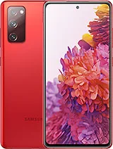
The Maxim MAX77705 charging controller manages 25W/45W charging in Samsung flagships. Compatible donor boards include Galaxy S20, S20+, S20 Ultra, Note 20, Note 20 Ultra, S20 FE, and Tab S7.
Compatible Donor Phones
These 4 devices share the exact same hardware component and can serve as scrap donors.

Engineering & Micro-Soldering Specs
Pinout dimensions, voltage rails, package footprint, and stencil requirements.
Workshop Harvesting & Rework SOP
Professional micro-soldering instructions for safe removal and installation.
Thermal & Short-Circuit Triage
Inject 1.0V to 1.8V on the primary VDD / VPH_PWR rail using a regulated DC bench supply. Inspect for hot spots using infrared thermal imaging or rosin atomization before removal.
Safe Desoldering & Thermal Shielding
Protect adjacent CPU and NAND flash ICs with polyimide Kapton tape and pure copper shielding. Apply RMA paste flux and heat with hot air at 345°C - 365°C with 40% airflow until balls liquefy.
Pad Cleanup & BGA Reballing
Clean scrap solder with copper desoldering braid at 320°C. Secure the chip in a Dedicated MAX77705 Laser Stencil, spread Sn63/Pb37 (183°C) leaded solder paste, and heat gradually at 280°C.
Alignment & Post-Install Verification
Align orientation pin 1 dot marker to the motherboard silkscreen. Reflow at 350°C until the chip naturally self-centers. Measure diode mode drops across surrounding inductors to confirm no shorts.
Maxim MAX77705 Fast Charging IC: Complete Technical Breakdown & Donor Guide
Read our technical teardown analysis for this component.